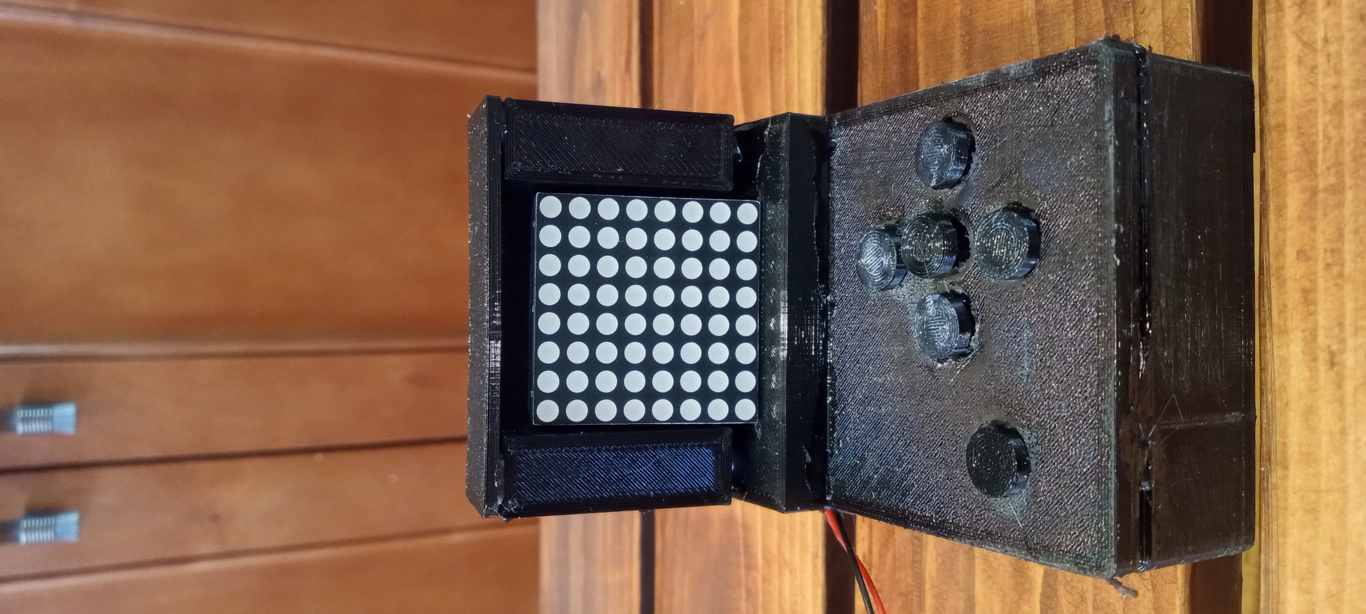
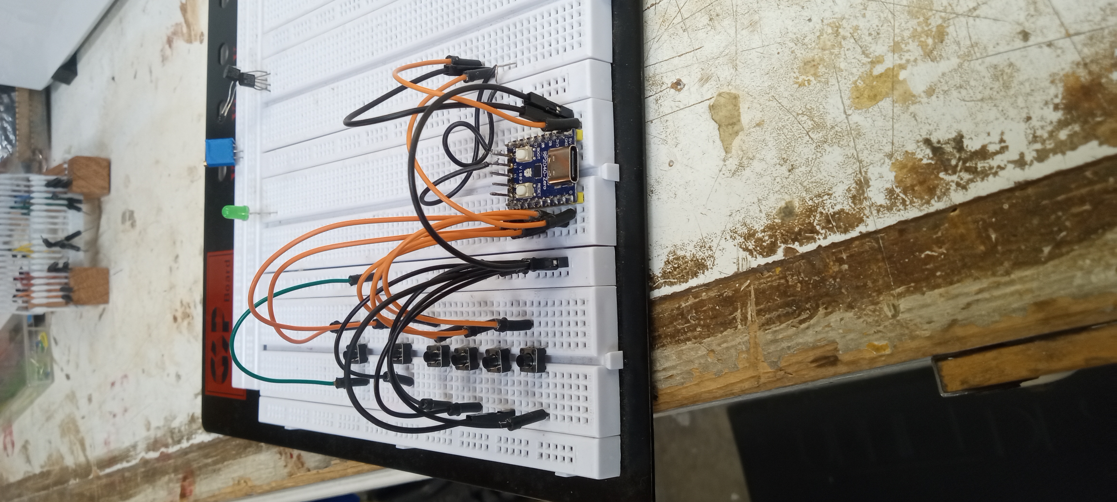
I began with a smaller LED matrix, but it turned out to be broken so I used a different larger one. I completed a bread board first without the LED matrix.
Project snapshot
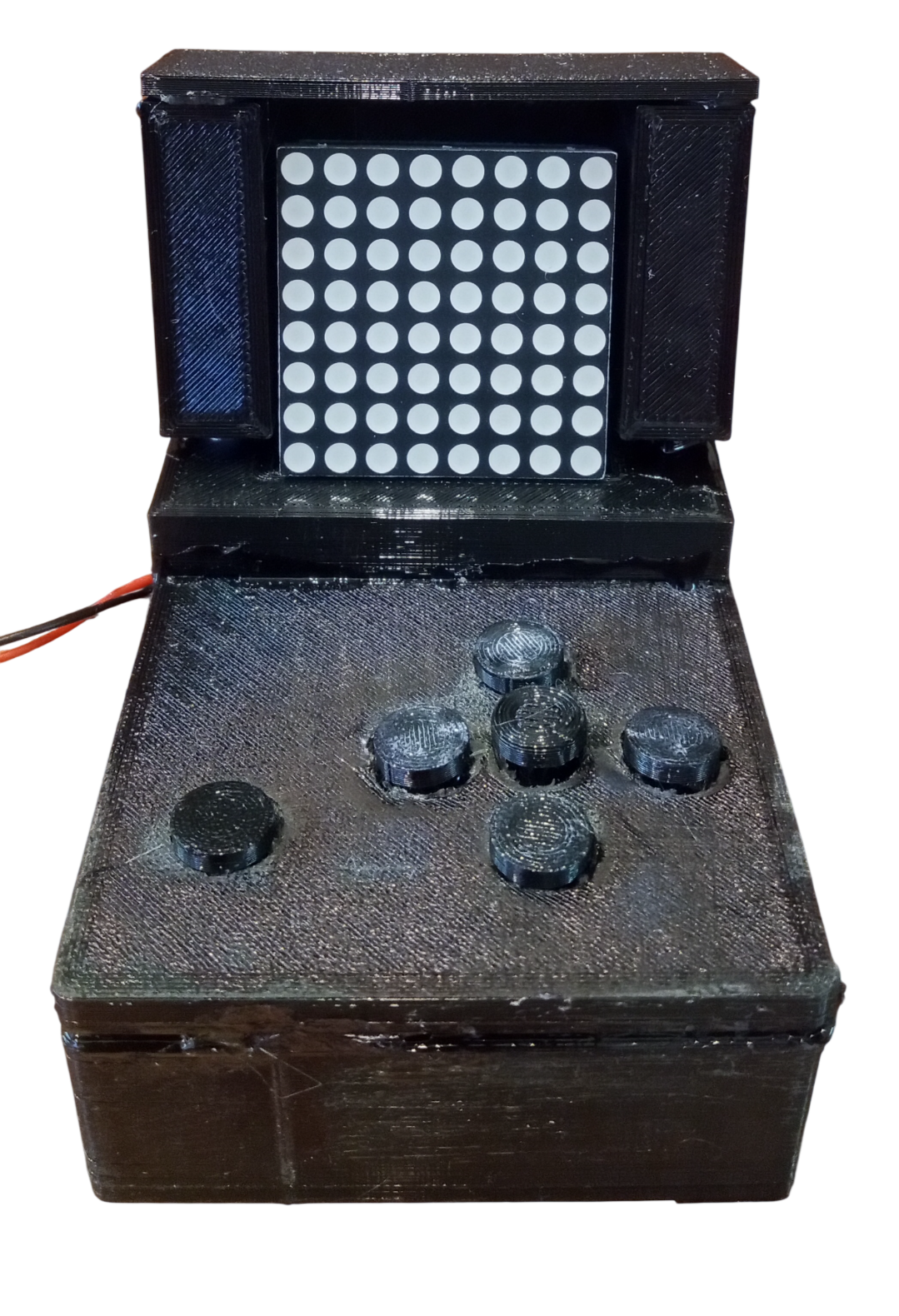
My LED tablet is my second Arduino project. There are six buttons. Four buttons are used as navigation: up, down, left, and right. A button in the center acts like an enter button and actually draws by turning on an LED. The button on the far left is a clear button.
The materials I used are:
Code
#include <Arduino.h>
#include <MD_Parola.h>
#include <MD_MAX72xx.h>
#include <SPI.h>

#define HARDWARE_TYPE MD_MAX72XX::DR1CR1RR1_HW
#define DATA_PIN 6
#define CLK_PIN 8
#define CS_PIN 7
#define MAX_DEVICES 1

MD_Parola displayText = MD_Parola(HARDWARE_TYPE, DATA_PIN, CLK_PIN, CS_PIN, MAX_DEVICES);

const int RIGHT = 27;
const int UP = 14;
const int DOWN = 28;
const int LEFT = 26;
const int ENTER = 15;
const int CLEAR = 29;

int xIndex = 0;
int yIndex = 0;

bool lastEnterState = HIGH;

bool lastRight = HIGH;
bool lastUp = HIGH;
bool lastDown = HIGH;
bool lastLeft = HIGH;

byte screen[8] = {
  0b00000000,
  0b00000000,
  0b00000000,
  0b00000000,
  0b00000000,
  0b00000000,
  0b00000000,
  0b00000000
};

void drawPixel(MD_MAX72XX *display, int x, int y)
{
  bool enterState = digitalRead(ENTER);

  if (lastEnterState == HIGH && enterState == LOW) {
    if (bitRead(screen[y], x) == 0) {
      bitSet(screen[y], x);
    } else {
      bitClear(screen[y], x);
    }
  }

  lastEnterState = enterState;
}

void readButtons()
{
  bool rightNow = digitalRead(RIGHT);
  bool upNow = digitalRead(UP);
  bool downNow = digitalRead(DOWN);
  bool leftNow = digitalRead(LEFT);

  if (lastRight == HIGH && rightNow == LOW) {
    yIndex -= 1;
  }

  if (lastUp == HIGH && upNow == LOW) {
    xIndex += 1;
  }

  if (lastDown == HIGH && downNow == LOW) {
    xIndex -= 1;
  }

  if (lastLeft == HIGH && leftNow == LOW) {
    yIndex += 1;
  }

  xIndex = constrain(xIndex, 0, 7);
  yIndex = constrain(yIndex, 0, 7);

  lastRight = rightNow;
  lastUp = upNow;
  lastDown = downNow;
  lastLeft = leftNow;
}

void drawPlayer(MD_MAX72XX *display, int x, int y)
{
  display->setPoint(y, x, true);
  delay(16);
  display->setPoint(y, x, false);
  delay(50);
}

void drawMap(MD_MAX72XX *display, const byte maze[8])
{
  for (int row = 0; row < 8; row++)
  {
    display->setRow(row, maze[row]);
  }
}

void setup()
{
  Serial.begin(9600);

  pinMode(RIGHT, INPUT_PULLUP);
  pinMode(UP, INPUT_PULLUP);
  pinMode(DOWN, INPUT_PULLUP);
  pinMode(LEFT, INPUT_PULLUP);
  pinMode(ENTER, INPUT_PULLUP);
  pinMode(CLEAR, INPUT_PULLUP);

  displayText.begin();
  displayText.setIntensity(3);
  displayText.displayClear();
  displayText.displayText("Mini Tablet", PA_CENTER, 90, 0, PA_SCROLL_LEFT, PA_SCROLL_LEFT);
}

void loop()
{
  MD_MAX72XX *display = displayText.getGraphicObject();

  if (!displayText.displayAnimate())
  {
    return;
  }
  else
  {
    readButtons();
    display->clear();

    if (digitalRead(CLEAR) == LOW) {
      for (int row = 0; row < 8; row++) {
        screen[row] = 0b00000000;
      }
    }

    drawMap(display, screen);
    drawPlayer(display, xIndex, yIndex);
    drawPixel(display, xIndex, yIndex);
    display->update();
    delay(50);
  }
}
I began with a smaller LED matrix, but it turned out to be broken so I used a different larger one. I completed a bread board first without the LED matrix.
After finishing the bread board, I soldered all the wires. Which was not too many considering how little components there were. Then I 3D printed a case and buttons.