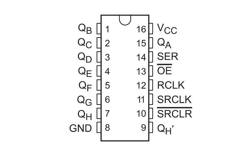
I began with finding a 74HC595 shift register. Then I connected it to my microcontroller. I made sure that I wired the pins of the shift register correctly by using a data sheet.
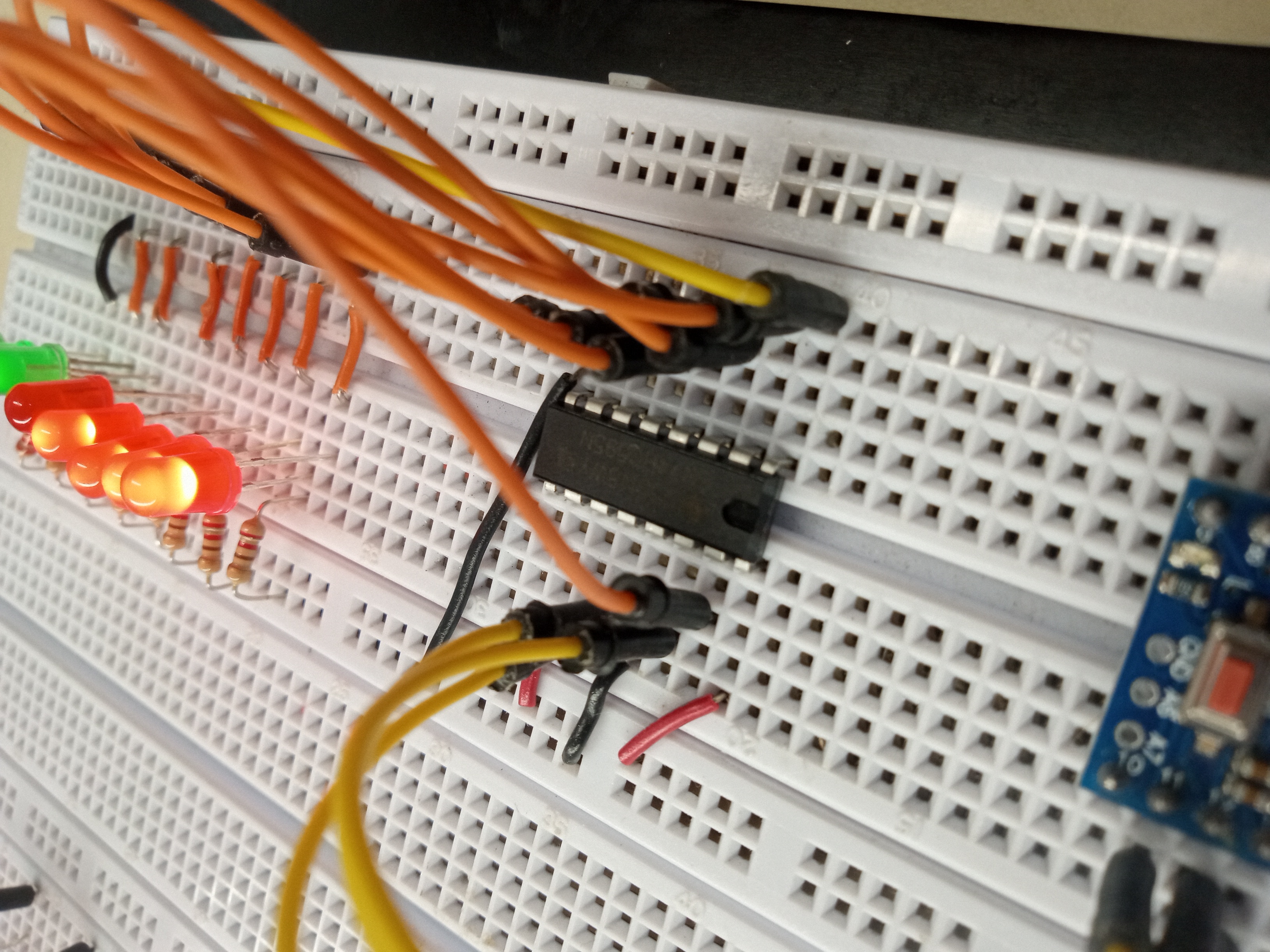
Project snapshot
I made this project to learn about shift registers. Shift registers help use fewer pins by indirectly powering something like an LED. Instead of saying "low" or "high", you pass a binary.
The materials I used are:
Code
#include <Arduino.h>

int latchPin = 12; // Latch pin of 74HC595 is connected to Digital pin 12
int clockPin = 13; // Clock pin of 74HC595 is connected to Digital pin 13
int dataPin = 11;  // Data pin of 74HC595 is connected to Digital pin 11

byte leds = 0; // Variable to hold the pattern of which LEDs are currently turned on or off

void updateShiftRegister();

void setup()
{
  // Set all the pins of 74HC595 as OUTPUT
  pinMode(latchPin, OUTPUT);
  pinMode(dataPin, OUTPUT);
  pinMode(clockPin, OUTPUT);
  delay(1000);
}

void loop()
{
  leds = 0; // Initially turns all the LEDs off, by giving the variable 'leds' the value 0
  updateShiftRegister();
  delay(500);
  for (int i = 0; i < 255; i++) // Turn all the LEDs ON one by one.
  {
    leds = i; // Set the variable 'leds' to the value of 'i'
    updateShiftRegister();
    delay(200);
  }
}

/*
 This function sets the latchPin to low, then calls the Arduino function 'shiftOut'
 to shift out contents of variable 'leds' in the shift register before putting the 'latchPin' high again.
 */
void updateShiftRegister()
{
  digitalWrite(latchPin, LOW);
  shiftOut(dataPin, clockPin, LSBFIRST, leds);
  digitalWrite(latchPin, HIGH);
}
#include <Arduino.h>
int latchPin = 12; // Latch pin of 74HC595 is connected to Digital pin 12
int clockPin = 13; // Clock pin of 74HC595 is connected to Digital pin 13
int dataPin = 11; // Data pin of 74HC595 is connected to Digital pin 11
byte leds = 0; // Variable to hold the pattern of which LEDs are currently turned on or off
void updateShiftRegister();
void setup()
{
// Set all the pins of 74HC595 as OUTPUT
pinMode(latchPin, OUTPUT);
pinMode(dataPin, OUTPUT);
pinMode(clockPin, OUTPUT);
delay(1000);
}
void loop()
{
leds = 0; // Initially turns all the LEDs off, by giving the variable 'leds' the value 0
updateShiftRegister();
delay(500);
for (int i = 0; i < 8; i++) // Turn all the LEDs ON one by one.
{
bitSet(leds, i); // Set the bit that controls that LED in the variable 'leds'
updateShiftRegister();
delay(500);
}
}
/*
This function sets the latchPin to low, then calls the Arduino function 'shiftOut'
to shift out contents of variable 'leds' in the shift register before putting the 'latchPin' high again.
*/
void updateShiftRegister()
{
digitalWrite(latchPin, LOW);
shiftOut(dataPin, clockPin, LSBFIRST, leds);
digitalWrite(latchPin, HIGH);
}#include <Arduino.h>
int latchPin = 12; // Latch pin of 74HC595 is connected to Digital pin 12
int clockPin = 13; // Clock pin of 74HC595 is connected to Digital pin 13
int dataPin = 11; // Data pin of 74HC595 is connected to Digital pin 11
byte leds;
void updateShiftRegister();
void setup()
{
// Set all the pins of 74HC595 as OUTPUT
pinMode(latchPin, OUTPUT);
pinMode(dataPin, OUTPUT);
pinMode(clockPin, OUTPUT);
}
void loop()
{
leds = random(0, 256);
updateShiftRegister();
delay(500);
}
/*
This function sets the latchPin to low, then calls the Arduino function 'shiftOut'
to shift out contents of variable 'leds' in the shift register before putting the 'latchPin' high again.
*/
void updateShiftRegister()
{
digitalWrite(latchPin, LOW);
shiftOut(dataPin, clockPin, LSBFIRST, leds);
digitalWrite(latchPin, HIGH);
}I began with finding a 74HC595 shift register. Then I connected it to my microcontroller. I made sure that I wired the pins of the shift register correctly by using a data sheet.
By using a USB to TTL converter, I could transfer my program into the microcontroller.
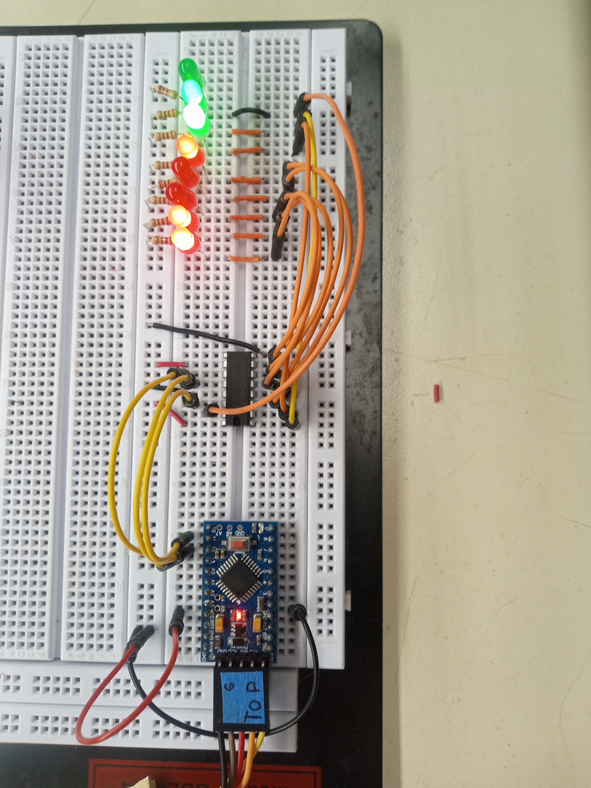
I made three different distinct patterns: a binary counter, a stacking effect, and an effect where a random set of LEDs light up.
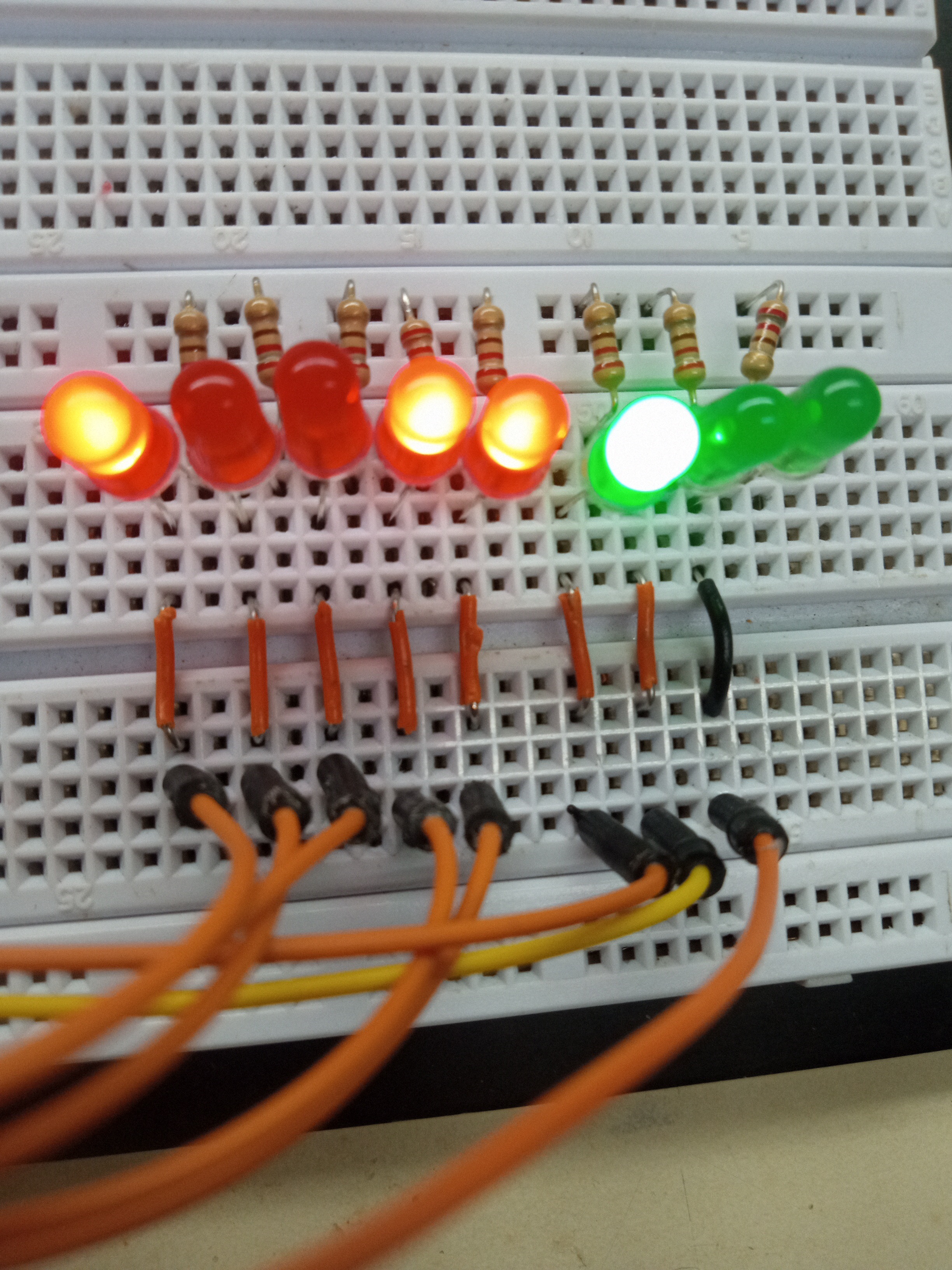
This is the binary counter.
This is the stacking effect.
This is the random effect.